Systematic machine-related deviations of machine tools can be recorded systematically, but deviations may still appear or increase during subsequent use due to environmental factors such as temperature or mechanical load. In these cases, SINUMERIK can provide different compensation functions. Compensate for deviations using measurements from actual position encoders (eg gratings) or additional sensors (eg laser interferometers, etc.) for better machining results. In this issue, we will introduce the common compensation functions of SINUMERIK. Practical SINUMERIK measuring cycles such as "CYCLE996 Motion Measurement" can provide comprehensive support for end users during the continuous monitoring and maintenance of machine tools.
Backlash compensation
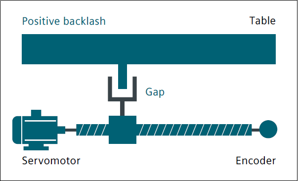
Intermittent or delayed force transmission occurs between the moving parts of the machine tool and its driving parts, such as ball screws, because a mechanical structure with no gaps will significantly increase the wear of the machine tool, and it is also difficult to achieve in terms of technology. . Mechanical play leads to deviations between the motion paths of the axes/spindles and the measured values of the indirect measuring system. This means that once the orientation is changed, the axis will move too far or too close, depending on the size of the gap. The table and its associated encoders are also affected: if the encoder is ahead of the table, it reaches the commanded position earlier which means the machine actually travels less distance. When the machine is running, by using the backlash compensation function on the corresponding axis, the previously recorded deviation is automatically activated during reversal, superimposing the previously recorded deviation on the actual position value.
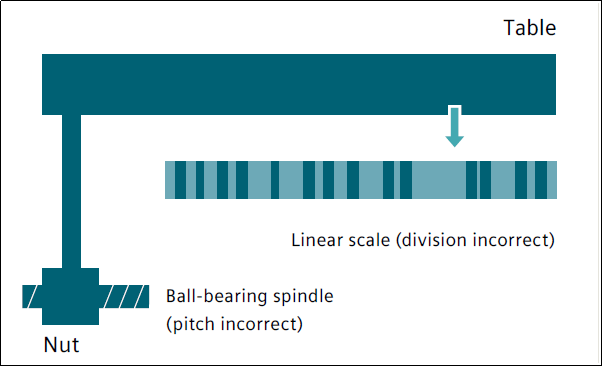
Lead screw pitch error compensation
The measurement principle of indirect measurement in the CNC control system is based on the assumption that the pitch of the ball screw remains unchanged within the effective stroke, so theoretically, the actual position of the linear axis can be derived from the motion information position of the drive motor. However, manufacturing errors in ball screws can cause deviations in the measurement system (also known as lead screw pitch errors). This problem can be further exacerbated by measurement deviations (depending on the measurement system used) and installation errors of the measurement system on the machine (also known as measurement system errors). In order to compensate for these two kinds of errors, an independent measuring system (laser measurement) can be used to measure the natural error curve of the CNC machine tool, and then the required compensation value is saved in the CNC system for compensation.
Friction compensation (quadrant error compensation) and dynamic friction compensation
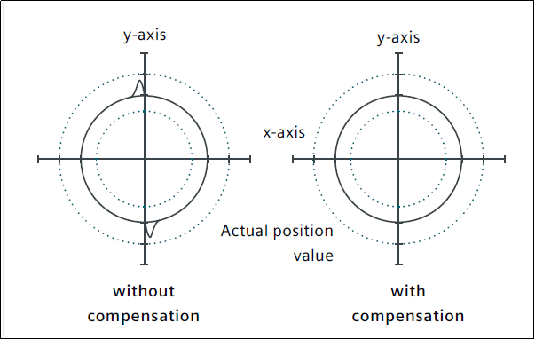
Quadrant Error Compensation (also known as Friction Compensation) is suitable for all of the above in order to greatly improve contour accuracy when machining circular contours. The reason is as follows: In a quadrant transformation, one axis is moving at the highest feed rate and the other axis is stationary. Therefore, the different friction behavior of the two axes can lead to contour errors. Quadrant error compensation can effectively reduce this error and ensure excellent machining results. The density of the compensation pulses can be set according to an acceleration-dependent characteristic curve, which can be determined and parameterized by a roundness test. During the roundness test, the deviation between the actual position of the circular contour and the programmed radius (especially during commutation) is recorded quantitatively and displayed graphically on the HMI. On the new version of the system software, the integrated dynamic friction compensation function can perform dynamic compensation according to the friction behavior of the machine tool at different speeds, reducing the actual machining contour error and achieving higher control accuracy.
Sag and Angle Error Compensation
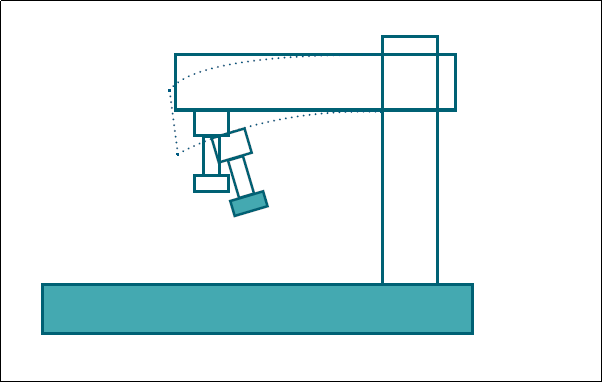
Sag compensation is required if the weight of the individual machine parts causes the moving parts to move and tilt, as it causes the associated machine parts, including the guide system, to sag. Angular error compensation is used when the moving axes are not aligned with each other at the correct angle (eg vertical). As the offset of the zero position increases, so does the position error. Both of these errors are caused by the dead weight of the machine tool, or the weight of the tool and workpiece. The compensation values measured during commissioning are quantified and stored in SINUMERIK according to the corresponding position in some form, such as a compensation table. When the machine tool is running, the position of the relevant axis is interpolated according to the compensation value of the stored point. For each continuous path move, there are basic and compensation axes. Temperature compensation heat can cause parts of the machine to expand. The expansion range depends on the temperature, thermal conductivity, etc. of each machine part. Different temperatures can cause the actual position of each axis to change, which can negatively affect the accuracy of the workpiece being machined. These actual value changes can be offset by temperature compensation. Error curves for each axis at different temperatures can be defined. In order to always compensate for thermal expansion correctly, the temperature compensation values, reference position and linear gradient angle parameters must be continuously re-transferred from the PLC to the CNC control via function blocks. Unexpected parameter changes are automatically eliminated by the control system to avoid overloading the machine and activate monitoring functions.

.jpg)